News
Yuxiang Display · Technical guide · Sources checked 2 November 2026
For a custom segment LCD, count the independently controlled display elements, choose a supported multiplex mode, then check the COM/SEG map and drive voltage. With M common electrodes and S segment electrodes, the addressing matrix can contain up to M × S elements. That is a capacity calculation. The approved glass drawing and electrode map determine the connections your instrument actually needs.
The following examples use Yuxiang's published FSTN display for multi-parameter instruments and STN display for energy meters. Their linked mechanical drawings provide the dimensions and connection details below.
| Parameter and source | Instrument example: drawing 16 | Energy-meter example: drawing 6 |
|---|---|---|
| Glass width × height, drawing | 40.00 ± 0.20 × 30.00 ± 0.20 mm | 52.00 ± 0.20 × 49.00 ± 0.20 mm |
| Thickness callout, drawing | 2.80 mm maximum | 2.80 mm maximum |
| Numbered connection positions, drawing | 32, arranged in two rows of 16 | 25, arranged in rows of 12 and 13 |
| Pitch within each connection row, drawing | 2.00 mm | 2.54 mm |
| Drive method listed on the product page | 1/4 duty, 1/3 bias | 1/4 duty, 1/3 bias |
| Operating voltage listed on the product page | 3.3 V | 5.0 V |
Sources: instrument drawing 16, meter drawing 6, and the two product pages, checked on 2 November 2026. Drawing dimensions and catalogue entries are identified separately. These public documents are references for selection; confirm the controlled revision and electrical specification for the ordered model. The mechanical images do not supply a complete COM/SEG assignment or a named driver IC.
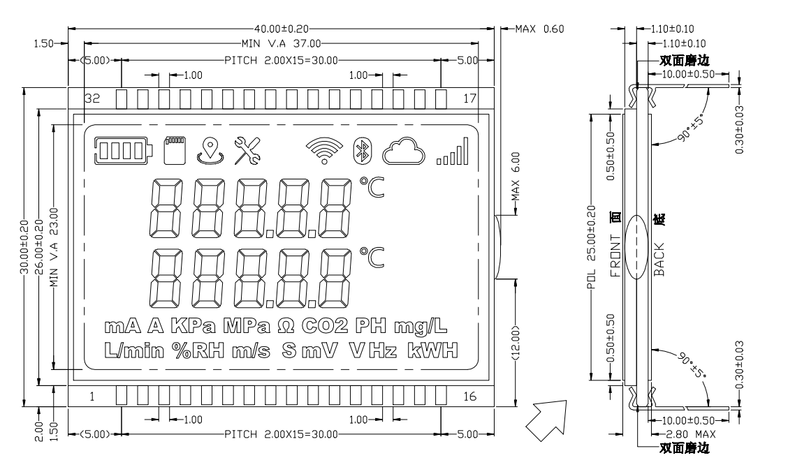
The instrument drawing includes digits, units and status symbols. Their independent control must be established from the electrode map.
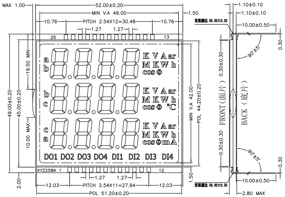
The connector layout differs from the instrument example even though both catalogue entries list 1/4 duty and 1/3 bias.
The two voltage entries explain why a matching duty and bias setting is only part of the selection. Confirm the meaning and allowed range of the specified LCD drive voltage. Separately check the controller supply and host I/O levels. A “3.3 V MCU” description does not establish that its LCD peripheral can drive a glass specified for another voltage.
An element is an area that the design allows you to switch independently: a digit stroke, decimal point, minus sign, alarm icon or bar. A printed unit made from several shapes might be one electrically grouped element. Its artwork alone does not establish the grouping.
For an illustrative instrument requirement, assume:
Six digits, each using seven independently controlled strokes: 6 × 7 = 42 elements.
Six separately controlled decimal points: 6 elements.
Eight separately controlled status icons: 8 elements.
The total is 56 independent elements. This is a calculation example, not a count of either pictured product. Include any additional minus signs, colons, range indicators or independently controlled bar sections in the real requirement.
For an ideal fully usable matrix, the lower bound is:
SEG outputs required = ceiling(elements ÷ COM outputs)
LCD electrode signals = COM outputs + SEG outputs
| Mode | COM outputs M | Minimum SEG outputs for 56 elements | COM + SEG signals | Matrix capacity |
|---|---|---|---|---|
| Static | 1 | 56 | 57 | 56 |
| 1/2 duty | 2 | 28 | 30 | 56 |
| 1/3 duty | 3 | 19 | 22 | 57 |
| 1/4 duty | 4 | 14 | 18 | 56 |
These are calculated electrode counts, excluding power, bias connections, unused or duplicated terminals, and a controller's host interface. Glass routing, package pin availability and the supported COM/SEG combinations can increase the required count or rule out a configuration. The 18-signal result is a design-screening number, not a pin assignment for either example product.
Duty identifies the multiplex arrangement. Four commons correspond to a 1/4-duty configuration. Silicon Labs' official LCD header, lines 75–84 explicitly distinguishes static, duplex, triplex and quadruplex operation and the corresponding COM groups.
Bias describes the voltage-level scheme used in the LCD drive waveform. It must agree with the glass specification and controller configuration. The STMicroelectronics STM32L0 LCD header, lines 215–246 defines duty and bias as separate settings, including LCD_DUTY_1_4 and LCD_BIAS_1_3.
These firmware references explain the configuration terms. They do not prove that any particular MCU package is electrically compatible with the Yuxiang examples. Check the exact controller or MCU data sheet, package pin assignment and permitted LCD voltage source before choosing the hardware.
A segment LCD uses the voltage difference between a SEG electrode and a COM electrode. The drive sequence must meet the glass supplier's AC and DC-balance requirements. Treating the glass as an LED and holding an element at a steady DC voltage is unsuitable. Duty also does not describe the backlight brightness or the percentage brightness of a visible digit.
Start with the required COM count, available SEG outputs, supported duty and bias combinations, and LCD voltage generation. Then check the package pins against the other functions used by the instrument. An MCU can expose fewer usable LCD outputs in a particular package or board configuration than a family-level feature list suggests.
For an external driver, separate the host-bus connections from the electrodes going to the glass. A serial interface can use relatively few host signals while the driver still provides many COM and SEG outputs. Confirm which circuitry is included in the quoted assembly.
Build a map that connects each user-visible function to a drawing label, glass terminal, COM/SEG pair and firmware bit. Give decimal points and alarm symbols explicit entries. Run a walking-element test that enables one mapped element at a time. Record the observed symbol alongside the expected symbol before approving the map.
Check normal readings, all-off and all-on patterns, negative values, decimal-point changes and every alarm state. Verify behavior during startup, sleep and wake transitions. Evaluate readability in the intended enclosure, viewing direction and lighting.
For faint or ghosted elements, record the controller settings and measure the differential waveform VSEG - VCOM with a suitable differential probe. Compare it with the approved waveform requirements. Check the mapping and actual LCD voltage before changing contrast settings. A drawing or photograph cannot establish whether a waveform is correct.
If low-temperature operation is required, use a defined stabilization condition and readable-screen criterion. The LCD cold-start test guide provides a way to separate optical response from electrical startup faults.
For battery-powered equipment, measure current at the defined system supply in normal display, sleep and wake states, with the backlight state recorded separately. A pin-count calculation cannot establish battery life. Preserve the sample identity, hardware and firmware revisions, supply, temperature, display pattern and actual results in the acceptance record.
Provide the required digits, units, icons and their independent on/off combinations; the enclosure opening and available installation space; viewing direction and lighting; interface constraints; drive conditions; and the required temperature range. Ask for the controlled drawing, electrode map and electrical drive specification before committing the PCB.
Use the segment LCD catalogue to discuss candidate constructions, then send the artwork and instrument requirements to Yuxiang Display. Identify which host electronics and backlight components should be included in the proposed assembly.
A segment LCD requires the specified alternating COM/SEG drive waveform. An LED segment is a light-emitting diode driven by a current-control circuit. Matching the digit shape does not make the electrical drive interchangeable. Confirm whether the offered product is glass alone or includes a controller and other electronics.
Count each independently controlled element. The worked example includes 42 digit strokes, six decimal points and eight icons, giving 56 elements. Electrically grouped shapes count according to the approved electrode map. A visible word or symbol can contain several shapes without requiring independent control of every shape.
They specify different aspects of the drive. A 1/4-duty configuration uses four commons; 1/3 bias specifies a voltage-level scheme. The controller needs a supported combination that matches the glass requirements. Neither value is a backlight-brightness setting.
The 18-signal result is a theoretical lower bound for four COM outputs and 14 SEG outputs. The real glass layout, terminal functions, unused connections and controller/package restrictions must also be checked. Use the approved drawing and map to determine the actual connector, rather than ordering from the formula alone.
Check the specified LCD drive voltage and how the chosen controller generates or receives it. Also check supply and host I/O limits separately. The catalogue voltage alone does not determine the complete circuit. Use the exact controller documentation and the approved glass specification to establish a suitable design.
Record the COM/SEG mapping, duty, bias, LCD voltage, frame settings and operating conditions. Compare the actual differential drive waveform with the supplier's requirements. Check all-off, all-on and walking-element patterns. Ghosting is an observation; the cause requires those checks rather than a blanket contrast adjustment.
The saving depends on the complete circuit and operating states. Measure the display/controller supply and any backlight load under defined conditions, then include the instrument's other loads and duty cycle. These product drawings do not establish a measured current or battery-life result.
Agree the artwork and independent-element list, drawing revision, mounting and connection details, electrode map, drive specification and acceptance conditions. Include unusual combinations such as negative values with alarms or different units. Record the responsibilities for controller, firmware and backlight integration in the quotation requirements.
Yuxiang: multi-parameter instrument FSTN product, with drawing 16.
Yuxiang: energy-meter STN product, with drawing 6.
Silicon Labs: LCD multiplex definitions, pinned source revision.
STMicroelectronics: separate duty and bias definitions, pinned source revision.
Dimensions, connection counts and pitch are transcribed from the published drawings; electrical entries are attributed to the product pages. The 56-element design and pin-budget table are labelled calculations. This article does not report physical sample measurements or a tested controller/glass pairing.